





- Machine de traitement d'huile de transformateur sous vide à deux étages
- Machine de traitement d'huile de transformateur sous vide montée sur remorque
- purificateur d'huile de lubrification (turbine / hydraulique)
- purificateur d'huile de transformateur sous vide à un étage
- système de purification d'huile de déshydratation sous vide
- purificateur d'huile isolante
- filtre à huile portable
- purificateur d'huile de type coalescent
- séparateur d'huile centrifuge à disque
- système de filtration d'huile diesel (carburant)
- presse filtre machine
- unité de pompe à vide
- système de purification de séchage à l'air
- équipements de test
- station de traitement de gaz sf6
- Cuves de filtration & accessoires
Acore Filtration Co. Ltd.
- Tél. : +86 132 06063693
- Email : sales@acorefiltration.com
- mobile et WhatsApp : +8613206063693
- Télécopieur : +86 23 8132 4618
- Ajouter : No.2, Jianhe Road, Banan District, Chongqing, China
Cas
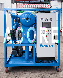
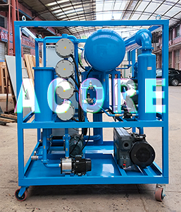
DVTP120(120LPM) Transformer Dielectric Oil Treatment Machine Sales to Chile
October 12,2026.
DVTP120(7200 liters per hour) Double stages high vacuum transformer Dielectric Oil Treatment Machine manufactured by Acore Filtration Co.,Ltd sales to Chile. In transformer manufacturing, maintenance,
and installation of high-voltage power equipment, the dielectric oil filtering equipment (usually composed of a roots pump
and a rotary vane vacuum pump is a key process device used to extract gas from
transformer oil tanks and reduce the moisture content of insulation materials.
Its selection and usage logic directly determine the insulation life and stable
operation of the equipment.
This article is based on the essence of engineering physics, outlining the
fundamental principles that must not be violated in selection and operation,
for reference by technical decision-makers and on-site engineers:
1. Understanding the physical logic, then match hardware parameters
The core value of vacuum Dielectric Oil Filtering Equipment does not lie in the
"ultimate vacuum value," but in maintaining continuous and stable
pumping speed and ultimate pressure during the long process of desuction and
venting of the transformer's solid insulation.
Primary (Front-stage Pump): Undertakes rough pumping tasks from atmospheric
pressure to medium vacuum stages, providing sufficient exhaust capacity.
Second stage (Roots pump): Starts under the base vacuum established by the
pre-stage pump, greatly increasing pumping speed and quickly removing gases
released deep into the insulating material.
Basic understanding of model selection: If you only focus on the unit's
ultimate vacuum (e.g., ≤5Pa) while ignoring the effective pumping speed within
the working pressure range (1~100Pa), the actual degassing time will far exceed
expectations or may even fail to meet process requirements.
2. Six basic considerations during the selection phase
Pump speed matching: Bigger is not better, but "slow start" is
prioritized
Principle: The Dielectric Oil Treatment Machine rated pumping speed should
match the transformer oil tank volume and total insulation material.
Empirically, the ratio of pumping rate (L/s) to tank volume (m³) should be
controlled within the range of 0.5~1.5.
Core risk: When the pumping speed is too high and there is a lack of intake air
regulation methods, the initial rapid pressure drop can trigger pressure
gradient shocks between layers of the insulation paper, causing fiber
displacement or damage. Therefore, adjustable intake valves must be installed
in the piping to support the two-stage operation of "slow drawing"
and full drawing.
3. Entry Protection: Pre-filter must not be
omitted
Functional requirements: Between the Insulating Oil Purifier's air inlet and
the transformer interface, a mechanical oil mist/dust collector (with built-in
stainless steel wire mesh or sintered filter element) must be installed.
Basis: There may be trace amounts of insulating oil or solid impurities inside
the transformer. If they enter the pump chamber directly, they will damage the
sealing oil film between the rotor gaps and degrade the ultimate vacuum degree.
The collector should be equipped with a visual level gauge and a bottom drain
valve for easy daily inspection.
4. "Sustaining capability" under extreme vacuum is more important
than "reaching the value"
Common misconception: Using the ultimate pressure the unit can draw as the
acceptance standard.
Correct perspective: Attention should be paid to the unit's own system leakage
rate (Pa·m³/s) after the main valve is closed. A high-quality Insulating Oil
Purifier should be able to maintain stable pressure, and if not continuously
running, it will not be able to maintain pressure. When selecting models,
suppliers should be required to provide static pressure holding test data.
5. Void breaking system: Must be equipped with a slow inflation device
Rigidity requirements: The unit should have its own inflation valve and drying
gas interface (nitrogen or deeply dried air is recommended).
Cause: When shutting down and breaking the air, if the air is introduced
directly, moisture will quickly enter the high-temperature pump chamber,
causing water vapor to condense and emulsify the pump oil, severely damaging
the preceding pump rotor and seals. Slow inflation (pressure recovery time ≥5
minutes) is a necessary design to protect the unit's lifespan.
6. Temperature monitoring and heat dissipation design
Core monitoring point: the exhaust port temperature of the preamplifier pump,
not the ambient temperature.
Selection consideration: Choose models with built-in temperature relay
protection, which automatically warns or reduces load when the exhaust
temperature approaches the oil flash point (usually ≤ 100°C). For high-load
continuous operation scenarios, forced air or water cooling heat exchangers
should be standard rather than optional.
7. Pump oil management friendliness (for oil-sealed pre-stage pumps)
Design evaluation: Observe whether the Dielectric Oil Filtering Equipment has a
structure that facilitates oil draining and refueling, and whether the oil
gauge window is clear and easy to read.
Basic understanding: After completing a large transformer degassing task,
dissolved trace water and acidic products in the pump oil need to be replaced
rather than replenished. Easy-to-maintain designs can significantly reduce
long-term operating costs.
Conclusion:
The selection of a Transformer Dielectric Oil Treatment Machine essentially involves balancing "continuous and stable pumping capability" with "friendliness to the transformer body." Understanding the above physical constraints and operational red lines helps avoid common pitfalls in selection and ensures that equipment investment translates into tangible process reliability.


 +8613206063693
 Rufus Huang
 sales@acorefiltration.com
 +8613206063693
 +86 23 8132 4618